|
The fun begins ...
|
|
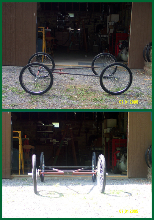
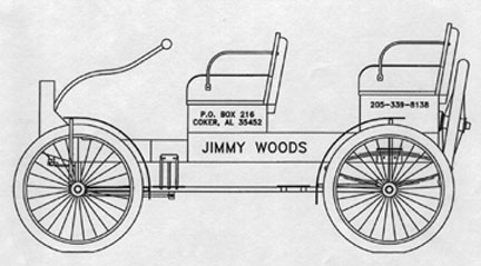
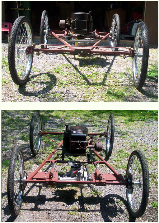
This is a basic four passenger Jimmy Woods' frame. The wheels are Worksman.
|
|

|
|

This is my design for the drive train, the last of many that I drew. It shows how I intend to slide the transaxle fore and aft in order to adjust the chain drive and make maintenance easy. The pictures that follow show the stages of the set up and construction of the drive train from beginning to end.
|
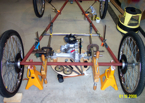
If you can look through the clutter of clamps you will see the rear view of the transaxle hanging from mounts that ride on the 3/4 inch round stock.
|
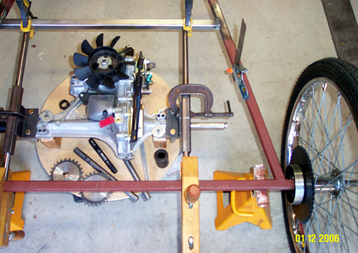
This view better displays the attachment of the transaxle to the bracket that will slide on the round stock. The angle iron that bolts to the transaxle will be welded to the 1 inch square tube where the C clamp is temporarily holding things together.
|
|
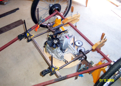
Another view of component placement.
|
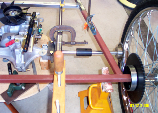
Here you can see the axle with coupler, axle extension and sprocket in relationship the the rear wheel and frame
|
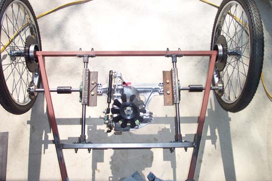
March 06, as the temperatures rise, I have made progress on the slide mount. Almost all of the basic parts are visible in this picture. I did redo the angle iron that bolts to the hydro. I found it needed to be longer to support a rectangular plate where the pillow block bearings will mount. The bearing mount plate will be fabricated soon. All parts still need to be finished. When I'm satisfied with the completed mount, everything will be disassembled, sandblasted, ground down, prettied up and painted with primer.
|
|
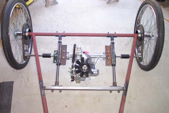
With the chains installed, I moved the mount forward and I am very happy to see that everything worked as planned.
|

|
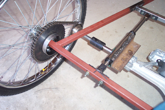
At present I am using locking collars to hold the hydro in the forward position. A proper locking/adjustment device will be fabricated.
|
|
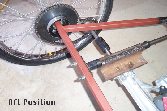
Here you see the slack in the chain with the mount in the aft position.
|
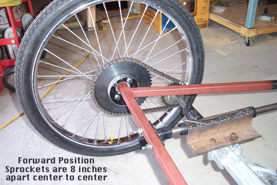
With mount in the forward position, the sprockets are 8 inches apart center to center.
|
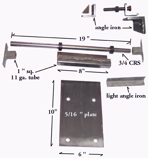
Here are the basic components to my slide mount. The dimensions are approximate and some parts on the picture are not in scale with other parts. The picture shows one side of the mount. The 5/16 " plates are of different lenghts because I offset the transaxle so the pulley would be on the center line of the frame.
|
|
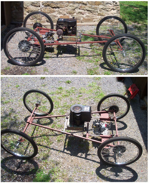
June 2006, I have the transaxle slide mount in place and the engine mounted.
|
|
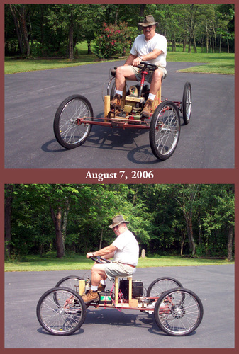
This is a picture of a test drive. The first test drive was about a month prior to the date on the picture. Once I finished the drive line, I decided it wouldn't be smart to continue with other parts of the carriage if what I had already constructed did not operate properly. So I made a temporary seat, added a steering wheel, cranked her up and away I went, although, very cautiously. The good news is; everything worked well.
|
|
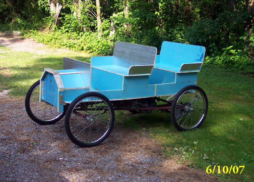
I am not a carpenter, however, given enough time and wood, I can do an adequate job. But before I started sawing on expensive wood, I purchased 2 sheets of 1/2" X 4' X 8' foam board insulation and put together a body. The picture above is the 1st of three mock-ups I made.
|
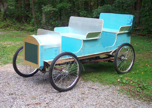
This is the 3rd rendition of the body Mock-up. Sharp angles have been replaced with curves. The various panels of this mock-up will be used to make permanent templates for the final wood body.
|
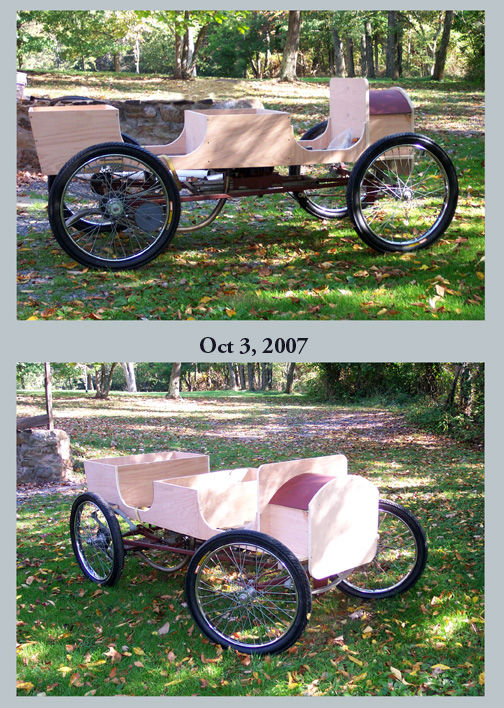
On August 10, 2007, I finally purchased the wood to construct the body. I disassembled the foam board mock-up and used the panels as templates. The picture above, dated Oct 3, 2007, is the progress I've made to date. I actually got to this point in mid September and obviously I have a long way to go. But I'm in no hurry. I make enough mistakes without trying to hurry.
|
|
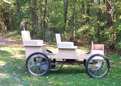
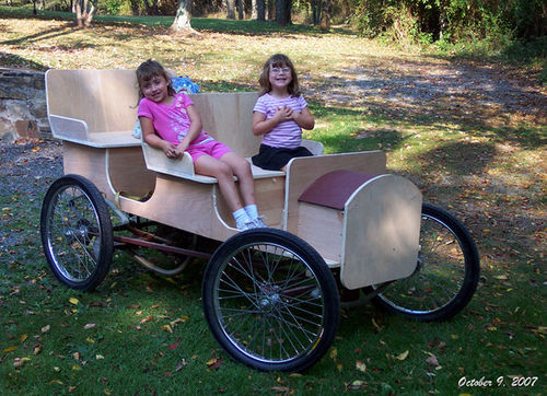
As of October 9, 07, if all else fails, I now have a nice place to sit down.
|
|
|
|
|
|
|
|
|
|
|


